Are you confused by why an 18650 cell labeled 3.7V suddenly reads 4.2V on a multimeter?
This “voltage mystery” is one of the most common technical hurdles for product developers and engineers designing custom battery packs. Understanding the gap between nominal voltage and peak charge voltage isn’t just about electrical theory—it’s the foundation of product reliability, safety, and long-term cycle life.
At nuranu, we’ve spent over a decade helping industrial partners navigate the complexities of lithium-ion chemistry. In this full analysis, we’re breaking down the science of the 18650 voltage curve, the critical role of the Battery Management System (BMS), and how to optimize your power systems for maximum performance.
Let’s dive into the data.
Decoding the Terminology: Nominal vs. Peak Voltage
I often encounter clients who are confused when their “3.7V” battery reads 4.2V on a charger. This isn’t a malfunction; it is a fundamental characteristic of Lithium-ion chemistry. To manage your power systems effectively, you must understand that an 18650 battery does not stay at one fixed voltage. Instead, it operates within a specific window.
What is Nominal Voltage (3.7V)?
The 3.7V nominal voltage is the average operating voltage of the cell during its discharge cycle. It is the “middle ground” where the battery spends the majority of its runtime. When we design 18650 cell specifications for industrial use, we use 3.7V as the baseline for calculating energy capacity (Watt-hours).
- The Midpoint: It represents the state of charge (SoC) at roughly 50%.
- Standardization: Most global manufacturers label cells as 3.6V or 3.7V to provide a realistic expectation of working power.
- Energy Calculation: (Nominal Voltage × Amp-hours) = Total Energy.
What is Maximum Charge Voltage (4.2V)?
When I talk about peak voltage, I am referring to the battery at 100% capacity. For a standard 18650 cell, the maximum charge voltage is 4.2V. This is the upper safety limit defined by the chemical stability of the lithium cobalt or manganese dioxide layers.
- Full Capacity: 4.2V indicates the cell is fully saturated.
- Charging Limit: Exceeding this threshold can lead to thermal runaway or permanent cell damage.
- The “Surface Charge”: Immediately after coming off the charger, the cell may sit at 4.2V, but it will naturally settle slightly lower once a load is applied.
The Cut-off Voltage (2.5V – 3.0V): Defining the “Empty” State
The “mystery” of 18650 voltage ends at the cut-off voltage. This is the floor of the discharge cycle. While the battery physically contains more energy below this point, extracting it causes irreversible chemical breakdown.
- Standard Cut-off: Most high-quality cells are rated for a 2.5V minimum.
- Safety Buffer: In my custom pack builds, I often recommend a 3.0V cut-off to extend the cycle life optimization.
- The Danger Zone: If a cell drops below 2.0V, the internal chemistry begins to degrade, often making the battery “dead” or unsafe to recharge.
| State of Charge | Voltage Reading (Approx.) |
|---|---|
| Full (100%) | 4.2V |
| Nominal (50%) | 3.7V |
| Empty (0%) | 2.5V – 3.0V |
The Science Behind the “Mystery”: Why 18650 Voltage Fluctuates
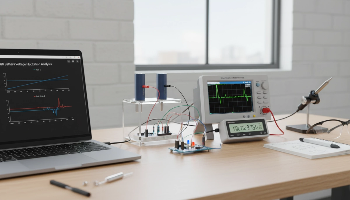
To truly understand the full analysis of 18650 battery voltage and the mystery of going from 3.7V to 4.2V, we have to look at what is happening inside the cell. The voltage isn’t a static number; it is a live reading of chemical potential.
Here is a breakdown of the core factors driving these voltage swings:
- Lithium-Ion Migration: The foundation of lithium-ion chemistry relies on ions physically moving back and forth between the anode and the cathode. When the battery is fully charged to 4.2V, the anode is packed with lithium ions. As you use the battery, these ions migrate to the cathode, causing the electrical potential (voltage) to naturally decrease.
- The Discharge Curve: Voltage does not drop in a perfectly straight line. During a standard discharge cycle, an 18650 cell drops quickly from 4.2V, settles into a long, flat voltage plateau around its nominal 3.7V, and then drops off sharply as it approaches empty. Tracking this curve is how we determine the accurate State of Charge (SoC).
- Internal Resistance Factors: Real-time voltage readings are heavily influenced by temperature and the physical load placed on the battery. Cold weather increases internal resistance, causing temporary voltage sag. Similarly, high-drain applications pull the voltage down faster. For example, when we design high-capacity systems like a 60V 12Ah 18650 lithium-ion battery pack for Harley electric scooters, we have to account for this internal resistance to ensure the voltage remains stable under heavy acceleration.
Understanding these internal dynamics makes it clear why an 18650 cell rarely sits exactly at 3.7V while in active use.
The Charging Cycle: How 3.7V Becomes 4.2V
Moving an 18650 cell from its nominal state to a full charge requires a precise process known as the CC/CV (Constant Current/Constant Voltage) charging protocol. This is a two-stage method designed to maximize energy density while protecting the lithium-ion chemistry.
- Constant Current (CC) Stage: The charger delivers a steady flow of current, rapidly raising the cell voltage from its depleted state toward the 4.2V peak.
- Constant Voltage (CV) Stage: Once the battery reaches 4.2V, the charger maintains that exact voltage while the current gradually tapers down. The battery is considered fully charged only when the current drops to a pre-set minimum.
Understanding these technical nuances is a vital part of our product knowledge base, as it ensures the longevity and performance of the custom packs we develop for our partners.
Preventing Thermal Runaway with Voltage Limits
Pushing an 18650 cell beyond the 4.2V limit is extremely dangerous. Overcharging causes chemical instability, which can lead to thermal runaway—a rapid, uncontrollable increase in temperature that may result in fire or explosion.
To mitigate this risk, we integrate high-precision Battery Management Systems (BMS) into every project. These systems act as a digital fail-safe, cutting off the charging current the moment the 4.2V threshold is reached. By strictly enforcing these voltage limits, we maintain a 98.5% quality pass rate and ensure that our 18650 systems remain safe for high-demand applications like robotics and power tools.
Engineering Implications for Custom Battery Packs
When we build custom power solutions, understanding the Full Analysis of 18650 Battery Voltage: The Mystery of Going from 3.7V to 4.2V is the foundation of a reliable build. We don’t just throw cells together; we calculate the exact series and parallel configurations needed to hit specific industrial targets.
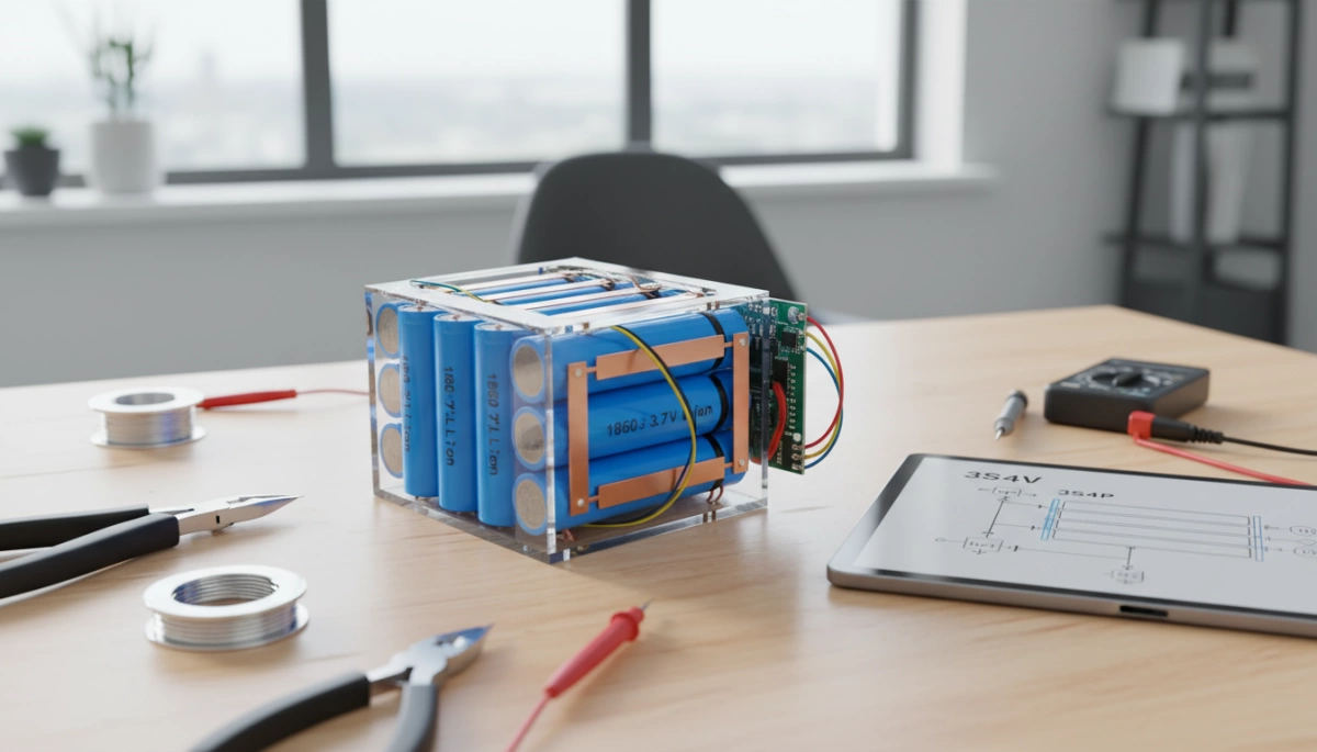
Scaling for Voltage and Capacity
To reach higher voltages, we connect cells in series. For example, a 3S configuration creates an 11.1V 4.4Ah 18650 lithium-ion battery pack by combining the 3.7V nominal ratings. If your project requires heavy lifting, like an electric scooter or industrial cart, we scale these configurations up to a 48V lithium battery system.
- Series (S): Increases voltage (e.g., 10 cells in series = 37V nominal / 42V peak).
- Parallel (P): Increases capacity (Ah) and current handling.
- The 4.2V Factor: We must ensure the charging hardware recognizes the peak voltage to avoid overstressing the pack.
Managing Voltage Sag and Cell Matching
In high-current industrial applications, “voltage sag” is a major hurdle. When a motor draws a massive load, the real-time voltage can drop significantly below the 3.7V plateau. We combat this through:
- Internal Resistance Sorting: We only group cells with identical resistance levels to ensure even discharge.
- Cell Matching: Every 18650 in a pack must have a uniform voltage window. If one cell hits 4.2V while others are at 4.0V, the entire pack’s cycle life optimization is compromised.
- Thermal Management: Keeping the cells cool prevents the chemical degradation that leads to premature voltage drops.
Precision at the assembly stage ensures that the swing from 4.2V down to the cut-off point remains stable, providing consistent power delivery for the end-user.
The Critical Role of the BMS in 18650 Voltage Management
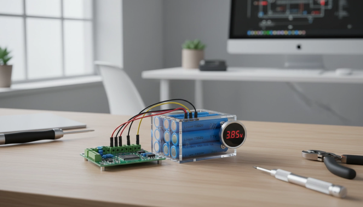
Managing the transition from a nominal 3.7V to a peak 4.2V requires more than just high-quality cells; it demands an intelligent Battery Management System (BMS). At Nuranu, our in-house R&D team treats the BMS as the “brain” of every custom battery pack, ensuring that the 18650 voltage swing remains within safe operational limits at all times.
Real-Time Monitoring of the 3.7V–4.2V Swing
A robust BMS provides continuous oversight of each cell’s State of Charge (SoC). This real-time data is vital for maintaining the health of the system:
- Preventing Overcharge: The system automatically cuts off power once the 4.2V threshold is reached to prevent cell degradation.
- Deep Discharge Protection: It ensures the voltage doesn’t drop below the critical 2.5V–3.0V limit, which preserves the battery’s long-term cycle life.
- Load Management: The BMS adjusts output based on the current voltage plateau, ensuring consistent performance for robotics or industrial power tools.
Cell Balancing and Safety Protocols
In a full analysis of 18650 battery voltage: the mystery of going from 3.7V to 4.2V is solved through active cell balancing. Without a BMS, individual cells in a series might hit 4.2V prematurely, causing the charger to stop before the rest of the pack is full. Our advanced programming ensures every cell reaches its peak capacity simultaneously, maximizing the energy density of the entire system.
We also integrate strict short-circuit protection and thermal management protocols. If a cell exceeds safe temperature ranges during the high-voltage charging phase, the BMS intervenes immediately. This level of engineering precision is why we maintain a 98.5% quality pass rate across our automated manufacturing lines, providing reliable power for over 50 countries.
Why Manufacturing Quality Dictates 18650 Voltage Stability
In my experience, the “mystery” of the 3.7V to 4.2V swing is only solved through rigorous manufacturing standards. If the chemistry isn’t pure or the assembly is sloppy, that voltage window becomes unpredictable. We focus on precision because even a minor fluctuation in internal resistance can lead to uneven discharge, reduced cycle life optimization, or worse, safety hazards.
Precision Testing and EOL Protocols
We don’t leave voltage stability to chance. Every cell we produce undergoes 100% End-of-Line (EOL) testing. This ensures that the 18650 cell specifications meet the exact requirements for your application before they ever leave the factory.
- Voltage Grading: Sorting cells by their precise open-circuit voltage (OCV).
- Internal Resistance Matching: Ensuring every cell in a pack reacts the same way under load.
- Capacity Verification: Confirming the energy density matches the label.
Global Certification Standards
To guarantee safety and performance in the US market, we adhere to the strictest global protocols. This isn’t just about paperwork; it’s about preventing thermal runaway and ensuring the battery can handle the stress of rapid charging.
- UN38.3: Essential for safe shipping and transport.
- UL 1642: The gold standard for lithium cell safety.
- IEC 62133: Global compliance for portable electronic applications.
Optimizing Voltage for Custom OEM Projects
For custom OEM projects, voltage stability is the backbone of device reliability. When we design a 11.1V 10Ah 18650 lithium battery for portable ultrasonic flaw detectors, we ensure the transition from peak to nominal voltage is smooth and predictable.
Low-quality manufacturing is the primary reason why many users end up asking do 18650 batteries go bad after only a few months of use. By maintaining high manufacturing standards, we ensure that the 3.7V to 4.2V range remains stable over hundreds of cycles, providing the consistent power your industrial equipment demands.
Frequently Asked Questions About 18650 Battery Voltage
Navigating the technical nuances of the Full Analysis of 18650 Battery Voltage: The Mystery of Going from 3.7V to 4.2V often leads to common operational questions. We have compiled the most frequent inquiries from our OEM partners to clarify how these voltage swings impact your applications.
Can I charge a 3.7V battery to 4.2V safely?
Yes. In fact, 4.2V is the standard maximum charge limit for a 3.7V nominal lithium-ion cell. Charging to this level is necessary to reach a 100% State of Charge (SoC). Our custom battery packs utilize advanced BMS programming to ensure the charger transitions from Constant Current to Constant Voltage (CC/CV) precisely at the 4.2V mark, preventing overcharge and maintaining cell health.
Why does my 18650 battery show 3.7V on the label but 4.2V on the charger?
The 3.7V figure is the nominal voltage, representing the average voltage the battery maintains during most of its discharge cycle. The 4.2V reading on your charger indicates the peak voltage when the cell is fully saturated. Understanding these ratings is a fundamental step in learning how to identify 18650 battery specifications for high-performance builds.
What happens if an 18650 battery drops below 2.5V?
Dropping below the 2.5V cut-off threshold enters the “over-discharge” zone. This can cause permanent chemical degradation, reducing the battery’s capacity and cycle life. If a cell stays in this state too long, it may become unstable or refuse to take a charge. This is often cited among the what are common problems with cordless vacuums and power tools where the device is stored with a depleted battery for extended periods.
Does higher voltage mean more power for my device?
Generally, yes. Power is the product of voltage and current (P=V*I). A battery at its 4.2V peak will typically deliver more “punch” or higher RPMs in motor-driven applications compared to when it sits at its 3.7V plateau. However, the device must be engineered to handle the specific voltage range of the battery pack to avoid damaging sensitive electronics.
- Nominal Voltage: 3.7V (The operational average)
- Max Charge Voltage: 4.2V (The full capacity limit)
- Cut-off Voltage: 2.5V – 3.0V (The safety floor)
- BMS Role: Monitors the 3.7V–4.2V swing to ensure stability and safety.